 How to resolve AdBlock issue?
 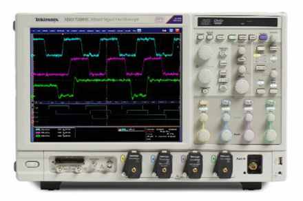 Today’s technology is fundamentally balanced on an increasingly fine line between the analogue and digital domains; as data speeds increase — both within and between devices — the ‘ideal world’ of fast, clean digital transitions becomes evermore difficult to achieve. This presents new and escalating challenges when verifying faster digital signals that exhibit more and more analogue-like features. As a result it is becoming necessary to remove the hard line between digital and analogue.
By adopting a mixed-signal approach to digital verification, engineers have greater visibility into the nuances that now dictate the stability and reliability of modern designs.
Mixed-Signal vs Logic Analyser
The traditional approach to verifying a digital design — a logic analyser — provides a range of powerful features that perfectly complement software debugging tools such as in-circuit emulators. These tools are employed predominantly by engineers tasked with ensuring a seamless integration exists between the software/hardware boundary.
In the same way, a mixed-signal oscilloscope (MSO) capable of providing basic logic analyser functionality can be seen as the tool to use when ensuring that the hardware/hardware (digital/analogue) boundary doesn’t introduce any of the potentially fatal functional errors now synonymous with high-speed digital signals.
For example, as the voltage excursion between a logic 0 and logic 1 continues to reduce, in order to achieve faster transition times and therefore faster transfer rates, the chances of small design deviations introducing operational anomalies increase. This promotes the possibility of instability, leading to unreliability.
Identifying and locating these deviations using traditional tools presents a challenge, as logic analysers typically present an abstraction or ‘representation’ of the signal being measured, rather than the full detail. Only through adding true analogue-like capture and display features can these ‘glitches’ be located and eradicated with confidence.
Any mixed-signal oscilloscope must be capable of measuring digital signals in an analogue world; edges aren’t clean, slew rates can vary and skew is commonplace. Accommodating these aspects of digital transitions requires an MSO that provides access to these parameters. The Tektronix MSO2000, MSO3000, MSO4000 and MSO5000 series of mixed signal oscilloscopes have been designed with these and other requirements in mind, but there are a number of specific features any MSO must offer as outlined in the following.
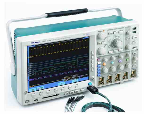
Fig 1. An MSO equipped with the flexibility to acquire and process ‘analogue’ signals in a ‘logical’ way can bridge the narrowing yet increasingly critical gap between the digital and analogue domains.
Thresholds and Skew
There are numerous digital logic families in use, which means not only do their voltage excursions vary but so too do their logic thresholds. Any instrument designed for the acquisition of these signals must, therefore, also be capable of differentiating between various logic families. MSOs used in the acquisition of digital signals should offer the ability to adjust the logic threshold measured, if possible on a per-channel basis, allowing circuits that employ several logic families — such as TTL and LVPECL, for example — to be debugged using just one instrument.
Adjustable logic thresholds are also a common feature within logic analysers, of course, but the benefit offered by an MSO is the simultaneous capture and display of the analogue features of the same signal.
Acquisitions
Logic analysers typically use two forms of acquisition: timing and state. Put simply, timing acquisition uses a fixed period to sample the logical state of a signal, while state timing uses a (potentially external) ‘trigger’ — often a clock signal generated by the circuit under investigation — to define a period during which the signal being measured is considered to be stable and logically valid. Of the two, an MSO would normally use a technique similar to timing acquisition, because using a high sample rate provides greater scope for capturing greater detail. The benefit here too is that, as the signal is sampled using an analogue probe, none of the information is ‘filtered out’ and can therefore be faithfully reproduced on-screen for engineers to examine.
Measurement & Verification
While a conventional digital storage oscilloscope (DSO) is capable of measuring and displaying logic signals as analogue waveforms, a significant benefit of MSOs is that they are designed to be ‘bus aware’; that is, they can group together signals and decode and display them as a digital bus.
This is highly beneficial when verifying a design and, in addition, some MSOs can go further to create an event table displaying the bus contents as either a binary or hex number, with each sample time-stamped, enabling simpler timing verification.
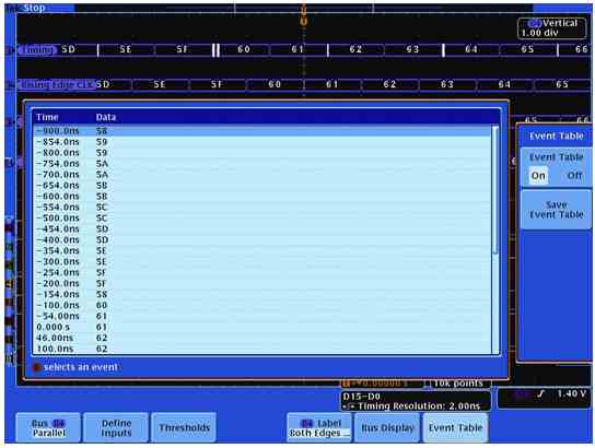
Figure 2. Decoded data is shown in an event table which is similar to a logic analyzer’s state acquisition display.
A further benefit of using high-resolution timing acquisition is that the contents of a bus can then be displayed in a simplified form; only displaying the status at valid times using a specified clock, while still preserving the core data which may be needed to detect errors.
Furthermore, MSOs are designed from a digital verification viewpoint, meaning they typically provide the capability to acquire a large number of inputs. For example, the Tektronix MSO series can decode up to 16 busses simultaneously, which may be parallel or serial and comprise I2C, SPI, USB, CAN, LIN, FlexRay, RS-242/422/485/UART, Ethernet, to name a few.
The ability to configure the logic thresholds and deskew the inputs means finding glitches becomes much simpler with an MSO. Crosstalk caused by the simultaneous transition of digital signals in close physical proximity, for example, can produce spurious false edges which would be difficult to capture using a logic analyser and difficult to correlate using a DSO. When captured and measured using an MSO, it becomes much simpler to correlate digital transitions against spurious crosstalk which exhibits random and analogue-like features.
Author: Hailey Percival, Technical Marketing Manager EMEA, Bench & Midrange, Tektronix