 How to resolve AdBlock issue?
 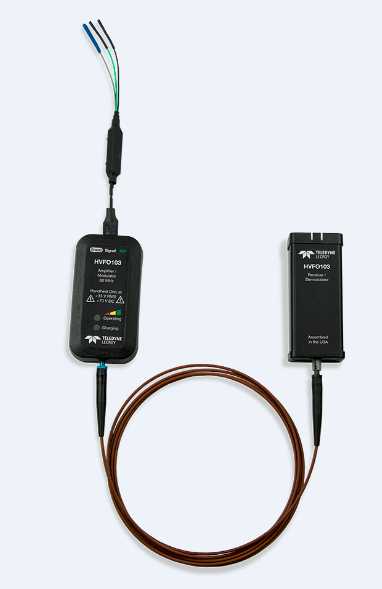 16 January 2017 - Teledyne LeCroy announces the new HVFO high voltage fiber-optically isolated oscilloscope probe. The HVFO probe further extends Teledyne LeCroy’s market leadership in the power electronics market, adding to other unique solutions such as the only HV differential probe rated for 1500Vdc common-mode testing, the industry’s only 8-channel, 12-bit resolution oscilloscopes, and Motor Drive Analyzers for three-phase electrical and mechanical power measurements.
The HVFO is an affordable, optimally designed probe for measurement of small signals floating on a HV bus in power electronics designs. Optical isolation between the probe tip and the oscilloscope input reduces adverse loading of the device under test (DUT); and also reduces noise, distortion, ringing, overshoots, and transients on the measured signal. It far surpasses the measurement capabilities and signal fidelity of both conventional HV differential probes and acquisition systems that rely on galvanic channel-to-channel and channel-to-ground high voltage isolation. Furthermore, it mitigates reliance on dangerous test setups that require floating the oscilloscope and probe, or investments in specialized isolated oscilloscope or data acquisition systems that result in other performance compromises.
The HVFO architecture is simple, with a single laser and fiber optic cable providing optical isolation and modulated signal + data communication. Multiple tips achieve different operating voltage ranges. The HVFO is small enough to fit in tight spaces, provides just enough performance for real-world needs, and is affordable enough to fit the tightest of equipment budgets.
Upper-side Gate Drive Signal Measurements
The gate drive circuit in a power electronics design is a series RLC circuit with parasitic capacitances across the semiconductor device. An upper-side device has an applied gate voltage floating above ground. Any measurement probe with high tip capacitance in parallel with the parasitic capacitance from the gate to emitter (CGE) or gate to source (CGS), and/or high impedance and low loop inductance in series with the gate drive impedance, will at best undesirably load the gate drive signal and at worst cause circuit malfunction. Measurement interference from the low-side device switching can also interfere with proper upper-side gate voltage measurement.
The HVFO has low tip capacitance and high input impedance, and because the amplifier is optically-isolated, the tip only has to measure the small signal gate-drive voltage. Therefore, there is approximately 1/100th of the loading compared to a conventional HV differential probe; and the superior noise and rejection provided by the high common-mode rejection ratio (CMRR), low lead loop inductance, and low attenuation permits the gate-drive signal to be faithfully reproduced in challenging environments.
Floating Control or Sensor Signal Measurements
It is difficult to measure floating control or sensor signals with conventional instrumentation, because a probe with low input impedance or high attenuation will load the DUT and adversely affect system performance or signal fidelity, result in too much noise in the measurement, or both. Furthermore, the HVFO’s low tip capacitance, which is charged only to the small-signal floating sensor voltage level and not the common-mode voltage, will provide better response for faster signals.
The HVFO will be priced less than $4000.
www.teledynelecroy.com/