 How to resolve AdBlock issue?
 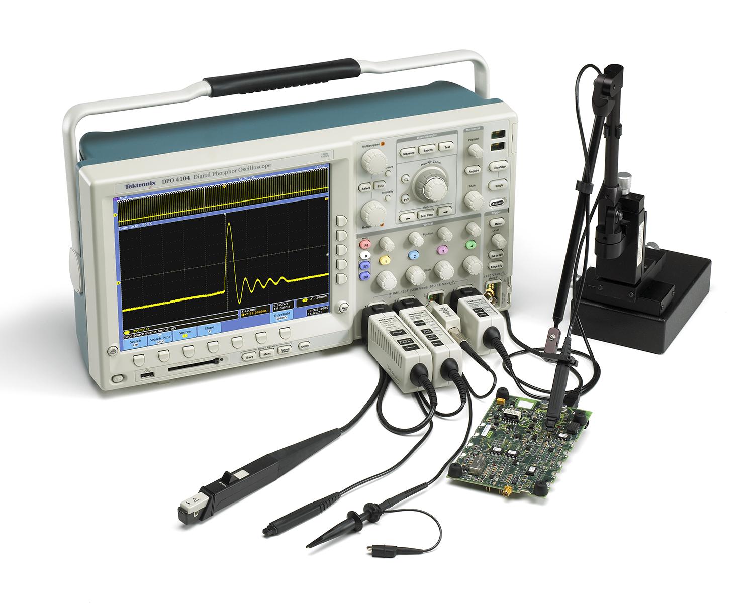 Signal measurement results can only be as accurate as the test and measurement tools in use. As clock rates and edge speeds of today’s electronic circuits increase, probing becomes a critical piece of the measurement system – the component that comes in direct contact with your circuit. This article looks at voltage probing considerations for embedded system and digital design debugging applications.
Connecting a probe to a circuit can affect the operation of the circuit, and an oscilloscope can only display and measure the signal that the probe delivers to the oscilloscope input. Thus, it is imperative that the probe have minimum impact on the probed circuit and that it maintain adequate signal fidelity for the desired measurements.
If the probe doesn’t maintain signal fidelity, if it changes the signal in any way, or changes the way a circuit operates, the oscilloscope sees a distorted version of the actual signal. The result can be wrong or misleading measurements. In essence, the probe is the first link in the oscilloscope measurement chain. Strength of the measurement chain relies as much on the probe as the oscilloscope. Weaken that first link with an inadequate probe or poor probing methods, and the entire chain is weakened. The ideal probe would offer the following key attributes:
- Connection ease and convenience
- Absolute signal fidelity
- Zero signal source loading
- Complete noise immunity
Connection to the physical test point should be possible with both ease and convenience. For miniaturized circuitry, such as high-density surface mount technology (SMT), connection ease and convenience are enabled through sub-miniature probe heads and various probe-tip adapters designed for SMT devices.
Absolute Signal Fidelity
The ideal probe should transmit any signal from probe tip to oscilloscope input with absolute signal fidelity. In other words, the signal, as it occurs at the probe tip, should be faithfully duplicated at the oscilloscope input. For absolute fidelity, the probe circuitry from tip to oscilloscope input must have zero attenuation, infinite bandwidth, and linear phase across all frequencies. In reality, such ideal requirements are impossible to achieve. Fortunately, for real-world signals in today’s embedded system designs, there’s no need for an infinite bandwidth probe. Chip-to-chip parallel interfaces, popular serial communications buses such as I2C or SPI, power switching waveforms, sensor outputs etc., can typically be viewed adequately with an oscilloscope + probe bandwidth up to 1GHz.
Measurement of high speed signals like PCIe, SATA, HDMI etc., are a different matter, and beyond the scope of this article.
Still, within a given bandwidth of operation, absolute signal fidelity is an ideal to be sought after.
Zero Signal Source Loading
The circuitry behind a test point can be thought of as, or modelled as, a signal source. Any external device, such as a probe, that’s attached to the test point will appear as an additional load on the signal source behind the test point, which draws signal current from the circuit (the signal source). This loading changes the operation of the circuitry behind the test point, and thus changes the signal seen at the test point.
An ideal probe causes zero signal source loading. In other words, it doesn’t draw any signal current from the signal source. This means that, for zero current draw, the probe must have infinite impedance, essentially presenting an open circuit to the test point.
In practice, a probe with zero signal source loading cannot be achieved. This is because a probe must draw some small amount of signal current in order to develop a signal voltage at the oscilloscope input. Consequently, some signal source loading is to be expected when using a probe. The goal, however, should always be to minimize the amount of loading through selection of the most appropriate probe.
Complete Noise Immunity
Compact Fluorescent Lights (CFL’s), fan motors, Switched Mode Power Supplies (SMPS) and backlight display drivers are examples of the many electrical noise sources in our environment. These sources can induce their noise onto nearby electrical cables and circuitry, causing the noise to be added to signals. Because of susceptibility to induced noise, a simple piece of wire is not an ideal choice for an oscilloscope probe.
The ideal oscilloscope probe is completely immune to all noise sources. As a result, the signal delivered to the oscilloscope has no more noise on it than what appeared on the signal at the test point.
In practice, use of shielding allows probes to achieve a high level of noise immunity for most common signal levels. Noise, however, can still be a problem for certain low-level signals. In particular, common mode noise can present a problem for differential measurements.
The Realities of Probes
Several realities prevent practical probes from reaching the ideal. To understand how this can affect your oscilloscope measurements, we need to explore the realities of probes further. First, it’s important to realize that a probe, even if it’s just a simple piece of wire, is potentially a very complex circuit.
For DC signals (0 Hz frequency), a probe appears as a simple conductor pair with some series resistance and a terminating resistance. However, for AC signals, the picture changes dramatically as signal frequencies increase. The picture changes for AC signals because any piece of wire has distributed inductance (L), and any wire pair has distributed capacitance (C). The distributed inductance reacts to AC signals by increasingly impeding AC current flow as signal frequency increases. The distributed capacitance reacts to AC signals with decreasing impedance to AC current flow as signal frequency increases. The interaction of these reactive elements (L and C), along with the resistive elements (R), produces a total probe impedance that varies with signal frequency. Through good probe design, the R, L, and C elements of a probe can be controlled to provide desired degrees of signal fidelity, attenuation, and source loading over specified frequency ranges. Even with good design, probes are limited by the nature of their circuitry. It’s important to be aware of these limitations and their effects when selecting and using probes.
Bandwidth and Rise Time Limitations
Bandwidth is the range of frequencies that an oscilloscope or probe is designed for. For example, a 100MHz probe or oscilloscope is designed to make measurements within specification on all frequencies up to 100MHz. Unwanted or unpredictable measurement results can occur at signal frequencies above the specified bandwidth.
As a general rule, for accurate amplitude measurements, the bandwidth of the oscilloscope + probe should be five times greater than the frequency of the waveform being measured. This “five-times rule” ensures adequate bandwidth for the higher-frequency components of non-sinusoidal waveforms, such as square waves.
Similarly, the oscilloscope must have an adequate rise time for the waveforms being measured. The rise time of an oscilloscope or probe is defined as the rise time that would be measured if an ideal, instantaneous-rise pulse were applied. For reasonable accuracy in measuring pulse rise or fall times, the rise time of the probe and oscilloscope together should be three to five times faster than that of the pulse being measured.
In cases where rise time isn’t specified, you can derive rise time (Tr) from the bandwidth specification with the following relationship: Tr = k/Bandwidth where k is 0.35 for oscilloscopes up to 1GHz bandwidth and 0.4 or higher for scopes over 1GHz.
Every oscilloscope has defined bandwidth and rise time limits. Similarly, every probe also has its own set of bandwidth and rise time limits. And, when a probe is attached to an oscilloscope, you get a new set of system bandwidth and rise time specifications.
Unfortunately, the relationship between system bandwidth and the individual oscilloscope and probe bandwidths is not a simple one. The same is true for rise times. To cope with this, manufacturers of quality oscilloscopes specify bandwidth or rise time to the probe tip when the oscilloscope is used with specific probe models. This is important because the oscilloscope and probe together form a measurement system, and it’s the bandwidth and rise time of the system that determines its measurement capabilities. If you use a probe that is not on the oscilloscope’s recommended list of probes, you run the risk of unpredictable measurement results.
Common voltage probe types:
Passive Probes are the most common, general purpose probe type. Designed to be durable and cost effective, passive voltage probes offer bandwidths to around 500MHz, a wide dynamic range and large input resistance in parallel with 10 – 15pF capacitive load.
The latest high-bandwidth passive voltage probes provide up to 1 GHz bandwidth with less than 4pF of capacitive loading. The extremely low capacitive loading reduces the adverse effects on circuits and is more forgiving of longer ground leads. And, with the probe’s wide bandwidth, you can see the high-frequency components in your signal which is critical for high-speed applications.
Active Single-Ended (FET) Probes provide a wide signal acquisition bandwidth and ensure reduced device under test loading. An active probe is the best choice when your application involves high-impedance, high-frequency circuit elements that demand minimal loading. DC offset capability allows you to use the probe’s full dynamic range when measuring AC signals in the presence of DC offset voltages.
Differential Probes enable the oscilloscope to display a complementary (differential) signal pair using a single channel. While a matched pair of single-ended probes may be used to make a differential measurement, a true differential probe typically gives higher performance, providing high CMRR, broad frequency range, and minimal time skew between inputs.
High Voltage Probes are used to safely and accurately capture real-time signal information from "elevated" or "floating" voltage systems High-voltage single-ended probes enable users to make ground-referenced, high-voltage measurements while high-voltage differential probes measure signals that are referenced to each other instead of ground.
Choosing the Right Probe
Because of the wide range of oscilloscope measurement applications and needs, there’s also a broad selection of oscilloscope probes on the market. This can make probe selection a confusing process.
To narrow the selection process, always follow the oscilloscope manufacturer’s recommendations for probes. This is important because different oscilloscopes are designed for different bandwidth, rise time, sensitivity, and input impedance considerations. Taking full advantage of the oscilloscope’s measurement capabilities requires a probe that matches the oscilloscope’s design considerations.
Additionally, the probe selection process should include consideration of your measurement needs. What are you trying to measure? Voltages? Current? RF Power? An optical signal?
By selecting a probe that is appropriate to your signal type, you can get direct measurement results faster. Also, consider the amplitudes of the signals you are measuring. Are they within the dynamic range of your oscilloscope? If not, you’ll need to select a probe that can adjust dynamic range. Generally, this will be through attenuation with a 10X or higher probe.
Make sure that the bandwidth, or rise time, at the probe tip exceeds the signal frequencies or rise times that you plan to measure. Always keep in mind that non-sinusoidal signals have important frequency components or harmonics that extend well above the fundamental frequency of the signal. For example, to fully include the 5th harmonic of a 100 MHz square wave, you need a measurement system with a bandwidth of 500 MHz at the probe tip. Similarly, your oscilloscope system’s rise time should be three to five times faster than the signal rise times that you plan to measure.
And always take into account possible signal loading by the probe. Look for high-resistance, low-capacitance probes. A 10 MΩ probe with 10 pF or less capacitance is good enough for many applications, but for high-speed digital circuits you may need to move to the lower tip capacitance offered by active probes.
Author: Trevor J. Smith, Technical Marketing Manager, Tektronix