 How to resolve AdBlock issue?
 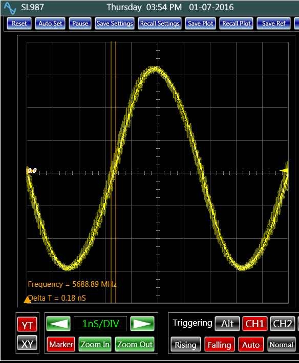 In the first part of this article a simple phase noise measurement technique with a resolution of 10 ps was explained. There are other techniques, which could enhance the performance of the measurement to sub-picoseconds. That is the subject of this article.
There are several applications, which demand very low clock jitter. Consider a 100 MHz 16-bit digitizer system. Ideally, the signal to noise ratio of this system in dB is given by:
SNR = 6.02 N + 1.76 = 6.02 * 16 + 1.76 = 98.08 dB; where N = number of bits
In practice, however, several factors reduce the noise performance of such a system. The SNR degradation could particularly be jeopardized at higher frequencies. One of the main reasons of high frequency digitization noise is the phase noise or jitter of the sampling clock. The following equation formulates the sampling noise caused by the clock jitter for a given signal frequency at full scale:
SNR= -20 log (2p fs * jRMS ) ; where fs = signal frequency & jRMS = RMS jitter
According to this formula, for a 10 ps clock jitter and a 50 MHZ signal, the SNR of the system is limited to about 85 dB, which is considerably worse than the ideal SNR. This calculation highlights the importance of keeping the clock jitter as small as possible. Therefore, with the ever increasing speed and performance level of electronic circuitry, the clock must be given a special attention. Obviously, with the higher frequency clocks, measuring the jitter noise becomes more challenging. Although there are various methods to measure sub picoseconds clock jitters, these methods are either application specific or demand complex procedures with expensive test equipments. Various examples of such techniques have been published [2, 3]. Since, usually, the clock is a periodical signal, the principle of equivalent time sampling can offer a simple alternative to these methods. In fact, the measurement technique in the first part of this article [1] was based on this concept.
In oscilloscopes, the real time sampling is converting the analog signal to digital bits at a fixed rate. There is no relationship between the sampling frequency and the frequency of the signal being converted. The time between the digital samples is exactly the same and equal to the sampling time. The digital representation of the original analog signal will then have missing sections between the consecutive samples. When the sampling frequency is much higher than the analog signal frequency, the digital construction of the signal is an accurate model of the input. However, as the input frequency increases, the constructed digital signal shows signs of discrepancy due to the missing information between the samples. For example, when the sampling frequency is exactly equal to the analog signal frequency, there is only one point of digital information available to construct the signal with. This will result in a DC line. Clearly, the digital model of the signal at higher input frequencies is far from the original signal.
The equivalent time sampling is referred to a sampling technique that is suited for periodical signals. In this technique, each time the analog input is sampled, the sampling clock is delayed by a predetermined amount (ΔT) with respect to a fixed point of the input. Therefore, the time resolution between the consecutive samples is effectively ΔT, yielding an effective sampling rate of 1/ ΔT that is independent of the frequency of the sampling signal. The tolerance of ΔT over the consecutive samples determines the accuracy of the reconstructed model. In practice, ΔT can be lowered to yield an effective sampling rate of 1000 GHz. This rate results in a 1 ps sampling time. Having this sampling time by itself is not sufficient to make fine jitter measurements. We also need a jitter free signal triggering mechanism. Hardware based signal synchronization causes a considerable amount of triggering noise. Software signal synchronization can offer a jitter free alternative. Figure1 and figure 2 compares these methods of signal synchronization.
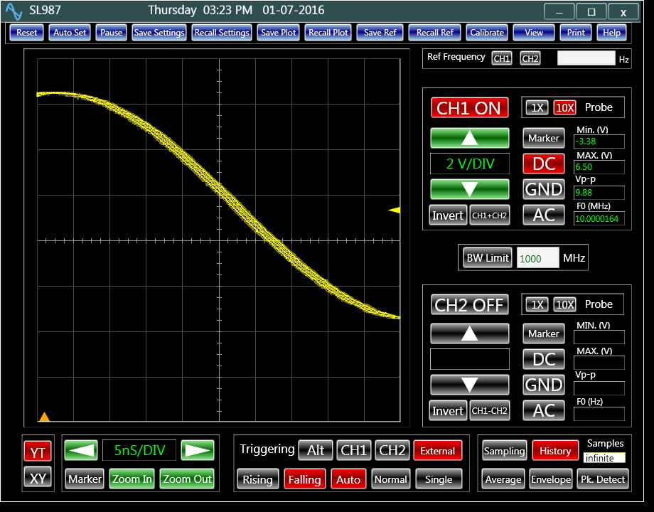 Figure 1: A hardware based triggering mechanism
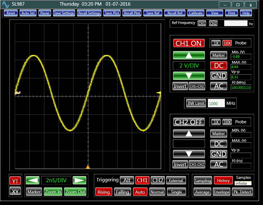 Figure 2: A software based triggering mechanism
Having a clean triggering mechanism, a uniform phase noise can be measured with a fine accuracy. Over consecutive cycles of the signals from the triggering point, the phase noise accumulates. The MATLAB simulation of the concept, shown in figure 3, illustrates the accumulation of jitter on the 1000th cycle from the triggering point.
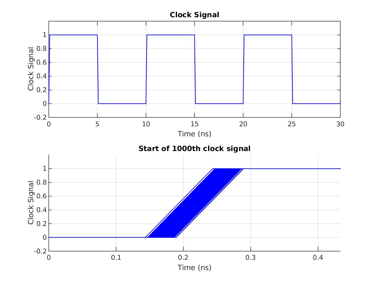 Figure 3: MATLAB simulation of phase noise accumulated over many cycles
Figure 3: MATLAB simulation of phase noise accumulated over many cycles
The following equations are then used to calculate the rms jitter [4]:
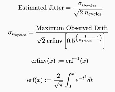
Figure 4 demonstrates a typical noise measurement based on this technique. For this plot, the oscilloscope was triggered on the falling edge of the signal at its middle level. Then, the measurement was performed at the rising edge of its 1000th cycle. From the plot the signal phase noise calculates to be .48 ps.
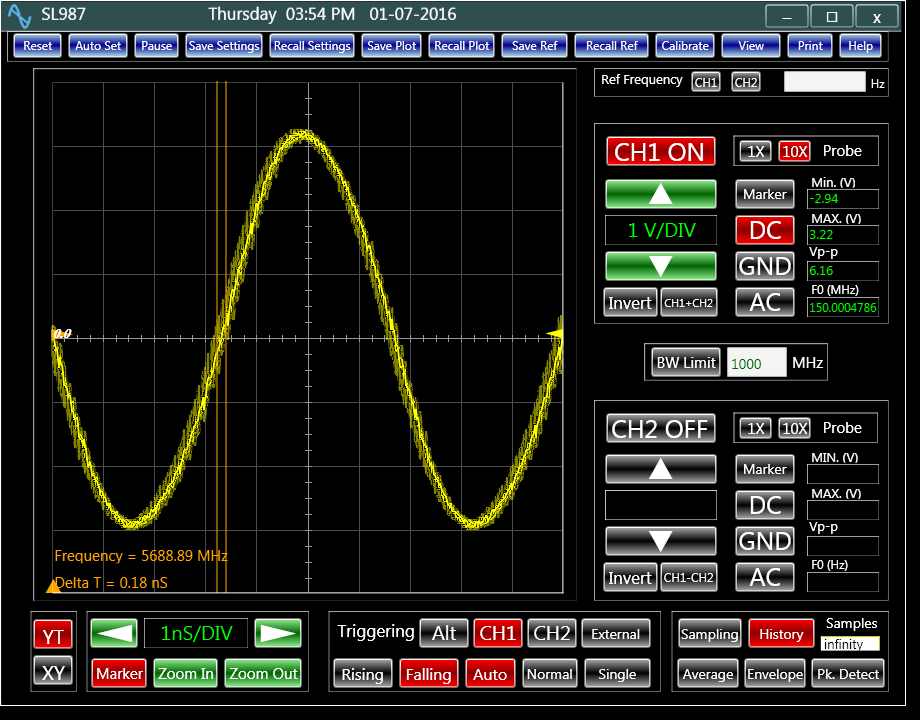 Figure 4: The accumulated jitter
As the speed of the electronics data processing increases, the clock noise becomes one of the dominants sources of error in the system. Maintaining a clean clock requires testing and measurement of various signal handling circuits. As explained in this article an oscilloscope can be used for this task; providing an alternative for cumbersome and expensive methods.
Author: Hamid Danesh (Project Engineer; Analog Arts Inc.)
References:
[1] Precision Phase Noise Measurement with an Oscilloscope: http://www.oscopes.info/background/2372-precision-phase-noise-measurement-with-an-oscilloscope
[2] Measuring Sub-Picosecond Jitter in A/D Converters for Wireless Applications:
http://www.eetimes.com/document.asp?doc_id=1230699">http://www.eetimes.com/document.asp?doc_id=1230699
[3] Measuring Phase Noise with a Spectrum Analyzer:
[4] Error function: https://en.wikipedia.org/wiki/Error_function